 FEATURED
Application Development & Modernization
Uplift enterprise IT with cloud-native modernization services that transform critical applications and empower peak performance.
Simplify the AI conversation. Build, scale, and optimize the way your business does AI.
Cut through the complexity of cloud technology and unlock its full potential with multi and hybrid cloud solutions and services.
Unlock collaboration that uplifts your organizations with cloud-based tools from Microsoft and Cisco to bring teams together.
Conquer security compliance complexities with targeted advising and assessment tailored to your company’s unique circumstances.
Consolidate your data management with an actionable plan for your business data.
Leverage DevOps and cloud-native principles to achieve business goals, enhance software delivery, and future-proof infrastructure.
Tailored solutions in Digital Commerce, Digital Marketing and overall Digital Strategy, unlocking your organization’s true potential.
Empowering better business starts with a better, modern data center.
Design a reliable networking solution around the requirements of your organization.
Transition from manual processes to streamlined, automated workflows for managing modern networks
Implement secure, scalable, and repeatable security measures shaped to serve your specific business needs.
Stay ahead of network needs and the competition with tailored optical transport and network infrastructure solutions.
 FEATURED
 FEATURED
 FEATURED
 FEATURED
 FEATURED
 FEATURED
RYAN HARRIS | Sr. Network Engineer
This is part one of a six-part series on the practical deployment of IPv6. This series will step through the various considerations needed to take your organization from a working IPv4-only network to a functioning and optimized dual-stack v4 and v6 network and move towards an IPv6-only network.
To learn more about why your organization needs to deploy IPv6, read the previous post: “Why Tech Execs Should Be Pushing for The Adoption of IPv6.”
The first step to successful IPv6 deployment is developing an IPv6 subnetting plan. Specifically, we want to define a hierarchical plan that allows us to meet the following goals:
Before putting pen to paper on your subnetting design, start off by taking stock of your existing network topology. Note your segmentation strategy, physical topology, existing IPv4 subnetting strategy, and network design.
Subnetting Considerations
Some boundaries will help us define our globally unique prefix size and how we delegate parts of our plan.
Assigning anything other than a /64 subnet mask to an end-user subnet will break SLAAC. You might be tempted to think “That’s ok, we were planning on using DHCPv6 anyways,” but this is an example of short-term thinking. The network design that you have today is likely not going to be the network design that you have forever.
Because the smallest prefix allowed in the global Internet routing table is a /48, best practice is to allocate at least a /48 anywhere that there might be a direct Internet connection currently or in the future. This means that even though branch sites might currently use a centralized data center for Internet breakout, they could be given direct Internet access with a technology such as SD-WAN, and therefore should be assigned no less than a /48.
I should acknowledge RFC 6177, which addresses the recommendation for only assigning /48 networks to all sites regardless of size. Their argument is primarily positioned against assigning /48 networks to home users, but it has valid reasoning that should be explored for the enterprise. For enterprise networks, I would still recommend using a consistent network size across the organization.
In addition to these items, there are good ideas that, if we integrate them into our subnetting plan, will improve our ability to meet our stated goals:
By only subnetting on nibble boundaries and allocating in sets of four bits, our subnetting plan can achieve our stated goal of decrypting the purpose of the subnet easily. Avoid allocating single bits because this can make it difficult to discern if a subnet is in one supernet or the other. For example, when allocating bits to a division of the subnetting plan, avoid creating something like /61, /57, or /53 subnet masks as it becomes difficult to determine if the hex digit 8 belongs to the subnet before or after.
With legacy IP thinking, it’s common to want to conserve addresses and make an allocation for a site only as large as it needs to be right now. The fault in this is twofold. Firstly it is short-term thinking and will cause you to change your subnet allocations the next time you change your network design. Secondly, there’s so much IPv6 space that conservation of addresses is completely unnecessary.
If you do this correctly, your subnetting plan should last your organization for decades.
Segmentations Concerns
You should, at this point, consider your network segmentation strategy. It’s common in many networks to create subnets per network use case, such as enterprise users, guests, phones, wireless, etc., and some organizations may implement technologies such as VRFs to assist with maintaining the segregation of traffic.
Your organization may have deployed network overlay technologies such as VXLAN that reduce the number of networks needed at a given site. Still, I recommend, even if this were the case, that you allocate enough networks in your subnetting plan to accommodate a more traditional routed design should you need it in the future.
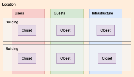
Location Based Subnetting
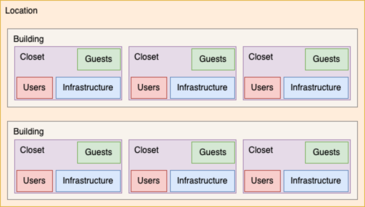
The location-based subnetting plan outlined here is meant to prioritize the location of a given subnet rather than its functionality. This plan assumes that segmentation technologies such as VRFs are not in use and allow for the cleanest summarization at site edges.
As you can see in the diagram, the hierarchy of the plan starts at the site location, and divides into building, floor, closet, and then subnet function.
Function Based Subnetting
The function-based subnetting plan outlined here prioritizes the subnet use over the floor or closet. This plan is best suited for organizations implementing macro segmentation policies using technologies such as VRFs as this allows for the cleanest summarization of those networks.
As you can see in the diagram the hierarchy of the plan starts with the site location as above, but then subdivides the subnet by function first before further subdividing by building, floor, and closet.
Function Based – Campus Subnetting
There is a twist on the function-based subnetting plan outlined above that can be used in situations where most of, if not all, the network resources are in a single geographic location. These campus networks are often interconnected to a singular location for egress to the internet.
Because of this reality of the network architecture, it becomes less important to prioritize the building or location of the subnet and more important to prioritize the function of the subnet. Generally, this subnetting design will be used where VRF’s are dedicated to a network function. Maintaining the separation of the VRF’s throughout the network is important.
Point-to-Point Subnets
Often, there is a need to assign a subnet for the purposes of connecting just two back-to-back routers, or a tunnel, or a singular host – a point-to-point link. In IPv4, this often required sacrificing precious space to wasted addresses that were unusable. In early network devices the smallest subnet that could be configured was a /30 network that allowed for 2 devices but wasted the network and broadcast addresses. Later network operating systems allowed for assigning /31 networks that were more space efficient by foregoing the network and broadcast addresses, but the fact remained that the IPv4 space was often still preciously little.
IPv6 has solved the space limitation, however, now most engineers are looking at point-to-point links as a huge waste of space. In addition to this space, there was some concern over possible neighbor cache exhaustion attacks as outlined in RFC 6583 where an attacker could open enough connections to bogus addresses on a subnet that the neighbor cache could be exhausted, causing a potential denial-of-service. Luckily, some research on the topic appears to show that most modern network operating systems do have some protection against this attack vector. However, you should keep in mind that this type of attack is a possibility.
While operating all your P2P links by subnetting a single /64 is possible, I would caution against doing that. For one, this approach isn’t hierarchical in design, does not subnet cleanly, and is not flexible should you ever need to expand a subnet to include more than two hosts. That said, it’s your network, you won’t break things if you use a /64 for all P2P subnets.
Let me show you the best way to assign P2P subnets: reserve a /64 subnet per P2P link, but only configure a /127 subnet mask. The /127 subnet mask is similar to the /31 subnet mask in IPv4.
It may be tempting to then assign the ::1 and ::2 addresses, however, if you’ll realize that ::1 and ::2 are actually in different /127 subnets, it fails to communicate. In fact, ::0 and ::1 are in the same /127 subnet while ::2 and ::3 are in another. I would recommend that you actually use ::A and ::B for assigning point-to-point addresses because these are in the same /127 subnet and are easy to remember.
Using /127 subnet masks, especially on external, unprotected networks is a great method to mitigate against potential neighbor cache exhaustion attacks. Check out RFC 6164 for an in depth look on the topic of using /127 subnet masks.
Requesting Space
After all of this, we need to request our address space. We have two options: Provider Independent (PI) and Provider Assigned (PA) space. Provider Independent is likely what most people think of when developing their IPv6 strategy. This is space carved out of the global unicast address range (2000::/3) by one of the regional registries (ARIN, RIPE, APNIC, AFRINIC, and LACNIC) and is owned by the requesting organization. If you decide to move from one ISP to another, PI space can be carried with you.
Provider Assigned space is most familiar to people from the IPv4 world, where you ask your ISP for space carved out of their IPv6 block(s). The downside of PA space is that should you ever stop using your ISPs services, you must either re-address your entire network or implement prefix translation at your network edge.
I’ll leave you with one last piece of advice: Let the nature of your network determine the amount of space you need rather than trying to fit the address plan to already existing space. In the long run, being too generous with your subnetting is better than being too stingy.